What's new

A little help please?

steffijade

Achiever
Joined
Jul 11, 2012
Messages
3,405
View attachment 3113

I've got a couple of tins that I'm going to mod up and now that I have my prewired connectors from Stealhtvape (thank you Rob ... much appreciated :encouragement: ) I'm about ready to make a start.

I would like to be able to add an on/off switch though to prevent accidental firing when I'm carrying em around in my bag.

I'm not sure on how to wire up said switch though ... my guess would be between the pos battery output lead and the pos input on the vv board.

Can anyone please tell me if this would work or offer another method?

Also, a recommendation or 2 for the actual on/off switch would be much appreciated.

Thanks. ;)
 
Last edited by a moderator:
You can get SP and DP (Single Pole or Double Pole) switches there are 6 contacts on the double pole. Wire a negative in to one of the centre posts and a positive in to the other one. On one pair of the outer pins wire the negative to the same side as the the negative input, and on the opposite of that pair, the positive out. The pair of unwired pins are your off position.
 
You can get SP and DP (Single Pole or Double Pole) switches there are 6 contacts on the double pole. Wire a negative in to one of the centre posts and a positive in to the other one. On one pair of the outer pins wire the negative to the same side as the the negative input, and on the opposite of that pair, the positive out. The pair of unwired pins are your off position.
Phew, thank heavens! That's my understanding too :rolleyes:
 
Morning Steffijade,

If you want to keep it nice and simple, I recommend these from Mark (Warlord). I use a very similar one. Just make sure you insulate the pins when you have soldered the wires, otherwise there is a good possibility of making a circuit if they touch the tin.

Also, break and switch the wire that makes contact with the tin body at the atty connector - I.e., if the outside of the connector has a ground (-) wire attached to it - break and switch the ground (-) wire from the battery holder to the board. That way you run virtually no risk of shorting the pins on the switch against the body of the tin.

Give me a minute and I'll see if I can do a diagram.

Cheers!

Lee

View attachment 2476

ALSO - feel free to PM me if you need a hand. :D
 
Last edited:
Morning Steffijade,

If you want to keep it nice and simple, I recommend these from Mark (Warlord). I use a very similar one. Just make sure you insulate the pins when you have soldered the wires, otherwise there is a good possibility of making a circuit if they touch the tin.

Also, break and switch the wire that makes contact with the tin body at the atty connector - I.e., if the outside of the connector has a ground (-) wire attached to it - break and switch the ground (-) wire from the battery holder to the board. That way you run virtually no risk of shorting the pins on the switch against the body of the tin.

Give me a minute and I'll see if I can do a diagram.

Cheers!

Lee
I was going to suggest that :rolleyes:
 
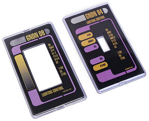
What about one of these?
aed3_startrek_plate_covers.jpg
 
I've just read the box on my piccie that concerns which wire to break and switch - can I clarify something:

What I mean is, if the negative/ground wire is attached to the outside of your atty connector from the output end of the board, break and switch the negative/ground leading into the VV board. If the positive is connected to the outside of the atty connector, break and switch the positive wire going into the VV board.

The paragraph in the piccie reads ambiguously - sorry.
 
Back
Top Bottom